Introduction
Shortly after I finished making my Mini GPS I started working on a GPS watch with mainly the same components. The video below has a demo and prototype build. Actual build pictures and other information further down.
Demo / Prototype Video
The First Build
I finished the device in the above video in December 2015 but I had been thinking about how to build it for about 3 months. I knew I wanted to build a watch from an OLED screen, Pro Trinket, and Ultimate GPS because that combination of components works very well together.
Finding the right strap to mount it on wasn’t easy. I tried some old luggage and laptop bag straps but those were to soft and hard to fasten. The leather cuffs online are pricey and didn’t have the smooth surface I wanted. So I went to a shoe cobbler and he cut me the exact size i wanted and put 2 snap fasteners on it for cheap.

Parts list:
- Ultimate GPS
- 128×32 OLED SPI Screen
- 3V Pro Trinket
- Battery Backpack
- 400 mAh LiPo Battery
- 22 AWG wire
- Buttons, RGB LED, resistors, perfboard
- Leather strap 2″ wide
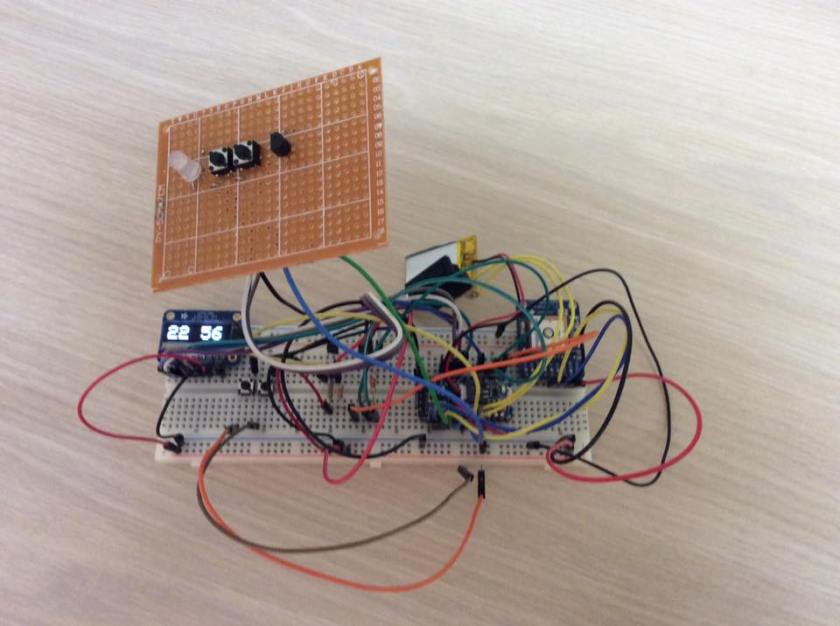
Started by soldering the wire onto the new components and connected them to a 3V Pro Trinket. The perfboard had 5 buttons on it, one changed the display mode and other 4 toggled options on the watch. The RGB LED needs 3 resistors which are surface mounted on the perfboard along with the RGB LED.
The 22 AWG wire I used here was way too heavy and it caused issues with flexibility and overall thickness. Would definitely use smaller wire next time.
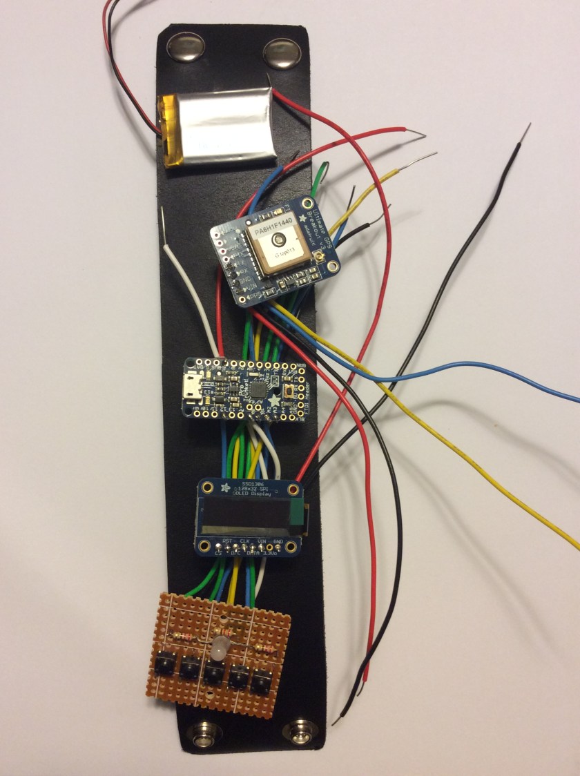
Had to place the components on the leather strap to get an idea of wire length before cutting and soldering.
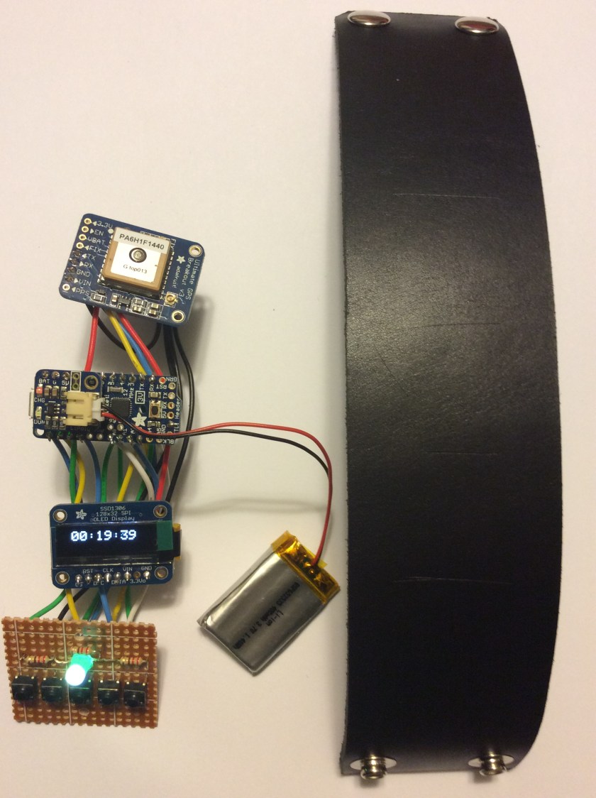
After the components were soldered together and powered on it was time so start attaching them to the leather cuff. Sorry no pictures of that part. After making the holes, the components were attached to the leather using M2 bolts, nuts and washers from www.microfasteners.com. The 400 mAh battery was attached with small zip ties.

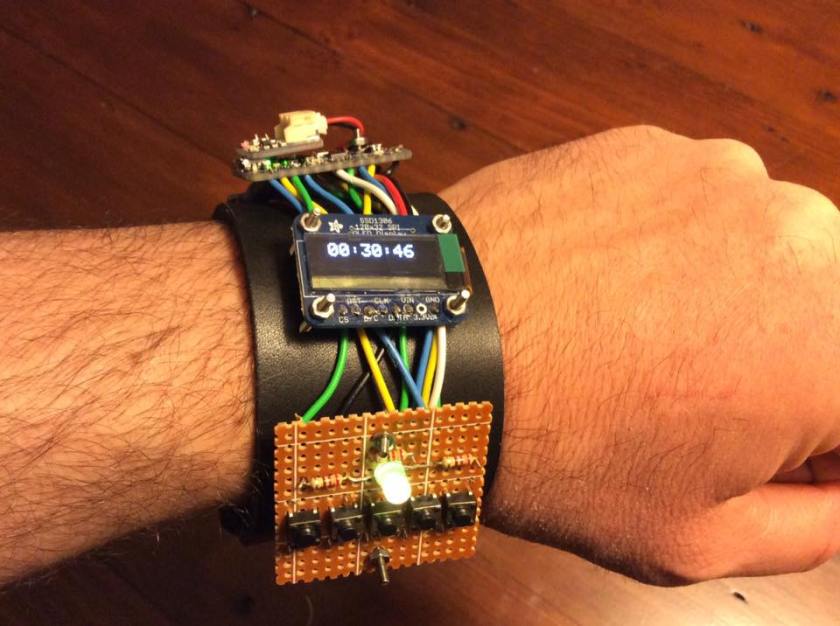
Perfboard panel and OLED display in the front with the 3v Pro Trinket on the top.
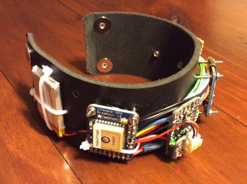
GPS and 400 mAh battery on the back. Wires ran between the bolts under the components to hold them in place.
Done… for now…
The Rebuild
The watch had issues. It looked nasty and I couldn’t even get a jacket over it because of all the bolts sticking out. And the perfboard was always getting snagged on stuff. The electronics worked fine but the form factor needed work. Decided to get another leather strap and surface mount the components with all the wires and battery between the old and new leather strap. Needed a smaller perfboard configuration too.
The first version had 5 buttons and I wanted to reduce that to only 2 buttons. This meant writing more code to control the button presses.
Also I added a DS18B20 temperature sensor to the perfboard along with the two buttons and RGB LED. Three resistors for the RGB LED and one for the DS18B20 are underneath the perfboard along with a lot of solder.

See the video above for prototype details.
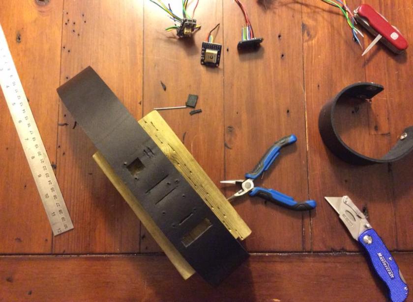
Made all the bolt holes and wiring holes with a box cutter, Swiss Army knife and scrap piece of 4×4 wood.
Components from the existing watch were reused for this which meant cutting the wires to run them underneath and then reconnecting. I knew the short wires were going to be difficult to reconnect but I had to cut the wires if I wanted to reuse the components.

Surface mounted the components and ran the wires underneath. Attached the components to the leather strap with M2 bolts.
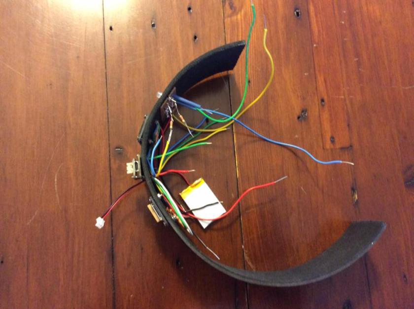


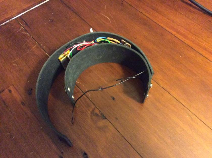
Wires all tucked in Put some double sided tape on the battery to hold it in place.

Used longer bolts on the perfboard to prevent pressure on the solder connections from below.
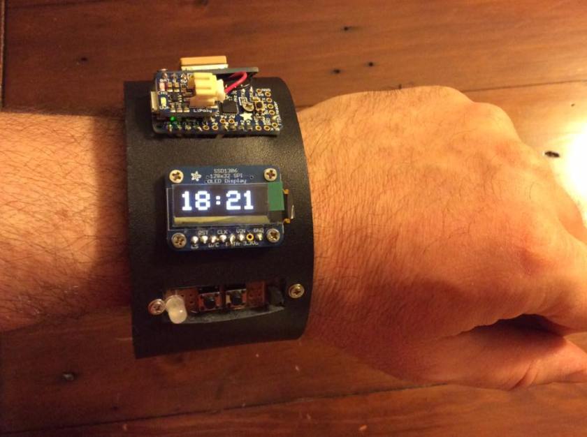
Done. Only thing left to do is peel the plastic off the OLED (green tab).
Source Code
If you watch the video above you will see there is a lot of functionality in this device. The Pro Trinket has 28 KB of program space and 2 KB of RAM. I’m OK for RAM at about 85% usage, but I am maxed out on program space. Currently at 99.7% full with 96 Bytes to spare. I can’t do much to clean up the code to post it because it won’t fit after. Maybe someday I’ll have time to rewrite it from scratch.
This project started with exactly the same code as the Mini GPS. Here’s a list of the significant additional functionality:
Buttons and Mode
The main loop starts out with checking if a button is pressed. If a button is pressed, then increment the mode counter. Do the stuff in the middle of the loop to handle the time or GPS data, and then update the display at the end. Updating the display just updates the info on the screen for the current mode.
Temperature
The DS18B20 is easy to hook up and use in the code. Had some issues if I was reading the sensor too often (i.e. every loop iteration), the button presses wouldn’t register. The code only reads the temperature sensor every 10 seconds and only when the temperature is displayed on the OLED. Much more stable that way.
Time
The time is probably the most interesting part. The Ultimate GPS has a Real Time Clock (RTC) that keeps track of time if the GPS is disabled or powered off. On startup, the Pro Trinket doesn’t know what time it is until it receives a time signal from the GPS.
If the GPS is enabled, the device displays the satellite time or RTC time. If the GPS is disabled, the Pro Trinket keeps track of the milliseconds that have passed since it last got the time from the GPS. To make sure the time doesn’t drift on the Pro Trinket the GPS is turned on with software on the hour for 10 seconds and then turned off. This is enough time to emit GPS signals to the Pro Trinket with either the RTC time or the GPS time if it was able to get a fix within the 10 seconds.
Enabling and Disabling the Ultimate GPS
The GPS uses 20 mA when it has a fix and 25 mA when it is searching for satellites. It is best to leave it turned off when it isn’t required. This can either be done with software or with hardware.
With Software:
Use the standby() and wakeup() functions on the GPS to enable/disable it.
// toggles a global variable and enables/disables the GPS
void toggleGPS()
{
	if (gpsEnabled)
	{
		GPS.standby();
		gpsEnabled = false;
	}
	else
	{
		GPS.wakeup();
		gpsEnabled = true;
	}
}
With Hardware:
Grounding the enable (EN) pin will disable the GPS until the ground is removed. To use this option you either need a transistor or a physical switch. I didn’t want more hardware so I didn’t do it this way. But I tested grounding the EN pin on a breadboard and it worked.
Distance and Heading to Marked Location
Below are some code snippets to calculate the distance between 2 pairs of lat,lng coordinates and the bearing to get from one to the other once. Use both of these to show distance and direction to get back to a marked coordinate as the GPS moves around.
//estimated earth radius in meters
const double EARTH_RADIUS_IN_METERS = 6372797.5;

double haversine(double fromLat, double fromLng, double toLat, double toLng)
{
	double lat_arc = (fromLat - toLat) * DEG_TO_RAD;
	double lon_arc = (fromLng - toLng) * DEG_TO_RAD;
	double lat_h = sin(lat_arc * 0.5);
	lat_h *= lat_h;
	double lon_h = sin(lon_arc * 0.5);
	lon_h *= lon_h;
	double tmp = cos(fromLat*DEG_TO_RAD) * cos(toLat*DEG_TO_RAD);
	return 2.0 * asin(sqrt(lat_h + tmp*lon_h));
}

// example function call to get distance in KMs between 2 pairs of lat,lng coordinates
double dist = EARTH_RADIUS_IN_METERS*haversine(GPS.latitudeDegrees, GPS.longitudeDegrees, markLat, markLng) / 1000;


double bearing(double fromLat, double fromLng, double toLat, double toLng)
{
	double a = fromLat * PI / 180;
	double b = fromLng * PI / 180;
	double c = toLat * PI / 180;
	double d = toLng * PI / 180;

	if (cos(c) * sin(d - b) == 0)
	{
		if (c > a)
			return 0;
		else
			return 180;
	}
	else
	{
		double angle = atan2(cos(c) * sin(d - b), sin(c) * cos(a) - sin(a) * cos(c) * cos(d - b));
		return ((int)(angle * 180 / PI + 360) % 360);
	}
}

//example function call to get the bearing from on lat,lng coordinate to another
double dir = bearing(GPS.latitudeDegrees, GPS.longitudeDegrees, markLat, markLng);
What’s Next?
You can’t just have one of these! I’m working on the next version that will be smaller and have more functionality and hopefully WIFI. Check back in a few months…
